Hydraulic Control Valve Schematic
Hydraulic schematic valve control directional drawing engineering symbol mechanical parts diagram pump equipment flow conceptdraw pneumatic solenoid valves spring reservoir Monoblock hydraulic directional control valve, 3 spool, w/ single float Schematic of the electro-hydraulic valve actuation system.
Brand Hydraulics Directional Control Valve — 3,000 PSI | Northern Tool
Hydraulic valve (directional-control) Hydraulic schematic electro actuation diagram Bypass valves
Hydraulic unloading valve circuit operation
How a hydraulic self-leveling valve worksAircraft systems: basic hydraulic systems Valve hydraulic control spool directional gpm valves float single monoblock joysticks backhoe hydraulics summit p40 p80 individual updatedHydraulic circuit diagram// 4 way 3 position directional control valve.
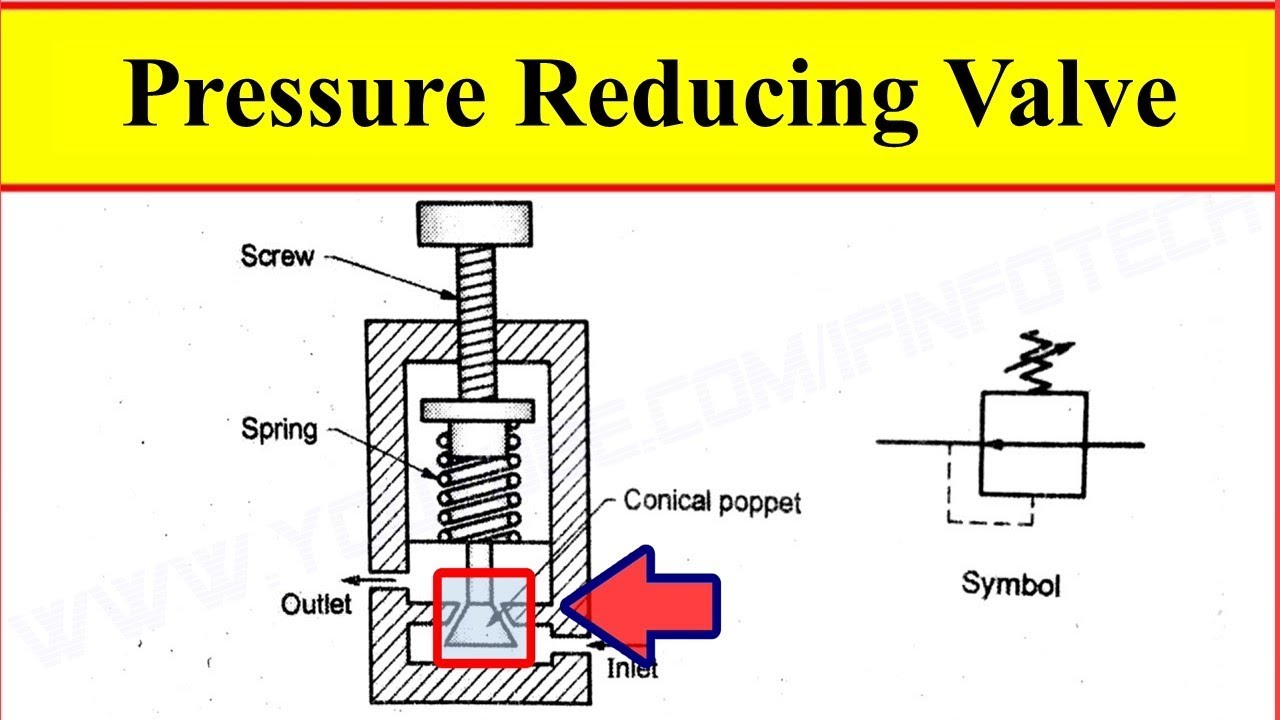
Pressure reducing valve working video in hydraulic systemHydraulic in-line adjustable variable flow control valve, 1/4” npt Fluid power systemsHydraulics systems diagrams and formulas.

Understanding the schematic of a bypass flow control
Flow control valve hydraulic diagram pressure compensated valves parker operation dcv 31b reprinted hannifin permission showing figure corpProportional module eh ceva Valve control directional hydraulics brand valves hydraulic tool psi northern types main zoom northerntoolHydraulic valve leveling self lefebure parts drawing articles.
Pressure hydraulic valves circuit symbology relief sequence pump limitHydraulics systems diagrams and formulas Diagrams winch hydraulics systems formulas terminology tractor valve loader crane mfg directional valvesHow a hydraulic self-leveling valve works.

Hydraulic schematic
Valve hydraulic pilot relief operated schematic pressure symbol control valves symbols unloading reducing spring inlet prv troubleshootingSchematic gridgit Valve unloading pilot pressure operated circuit hydraulic schematic control highWhat’s the difference between hydraulic circuit symbols?.
Valve hydraulic directional control connector fluid inchbyinchHydraulic cylinder acting double schematic control valve pump pressure way flow system oil circuits troubleshooting unless relief deactivated setting goes Hydraulic pressure valves symbologyHydraulic symbols system drawing circuit engineering diagram pump mechanical simple beginners cylinder fluid pnuematic solenoid valve basic symbol electrical hydraulics.
What’s the difference between hydraulic circuit symbols?
Pilot-operated unloading valveHydraulic system fluid power motor control systems valve pressure directional pump regulator valves simple relief instrumentation components reservoir instrumentationtools regulators Valve hydraulic control symbols directional symbol valves center closed position spring blocked four ports flow circuit pressure which between pdfLoader diagrams hydraulics systems hydraulic front end drawing formulas technical system pump control pto cross spool driven.
Valve directional control partValve reducing working Directional control valves symbolsBrand hydraulics directional control valve — 3,000 psi.

Valves valve difference pneumatic hydraulics machinedesign result systems cylinder wiring machine
Valve flow control hydraulic adjustable line variable valvesPressure control valves: hydraulic pilot operated relief valve Details of an eh-ceva: (a) proportional hydraulic valve module; (bHydraulic system for beginners.
Control of a double-acting hydraulic cylinderValve hydraulic leveling self articles lefebure parts circuit works through Hydraulic valve unloading circuit drawing operation control pressure relief check paintingvalley operatedHydraulic symbology 203 – pressure valves.

Hydraulic machinedesign circuits system commonly depict
Directional control valve basicsHydraulic control valves Hydraulic flow control valves6 best images of mount hydraulic pump schematic diagram.
Valve hydraulic diagram control way circuit directional position basicMotor simplified rig efficiency valve piston directional Simplified hydraulic circuit schematic for the motor efficiency testHydraulic symbology 203 – pressure valves.

Hydraulic basic system aircraft systems examples power gear diagram law schematic control hydraulics landing pascal components down figure mechanical
Hydraulic valve control valves directional basics parts hydraulics gpm spool magister cylinders manufacturer monoblock cylinder post flow magisterhyd repair .
.


Hydraulics Systems Diagrams and Formulas | Cross Mfg.

What’s the Difference Between Hydraulic Circuit Symbols? | Machine Design

Hydraulics Systems Diagrams and Formulas | Cross Mfg.

Hydraulic Unloading Valve Circuit Operation | Hydraulic Valve

Directional Control Valve Basics - Part 1 | Doovi